Leak Detection using Logic Gates
Use logic gates and GPIO pins to build leak detection safety interlocks for aquarium and hydroponic water systems with Krill.
Krill and The Movement of Water
Part 1: Leak Detection and Logic Gates.
First we’ll connect to our city water source. In our case we have a whole house water filtration system that provides clean fresh water to all our systems.
From here we can use Krill to control the flow of water to our various systems. The first stop will be to keep my aquarium topped off with fresh water to compensate for evaporation. Later, we’ll pump water out of the aquarium to the vivarium to maintain proper humidity levels for E and provide clean, warm water for her jacuzzi.
Parts List:
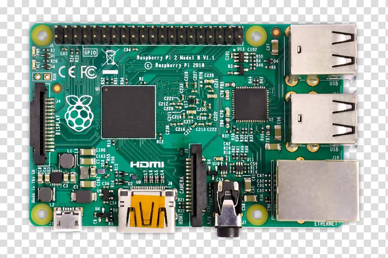
- A Raspberry Pi running Krill Server.
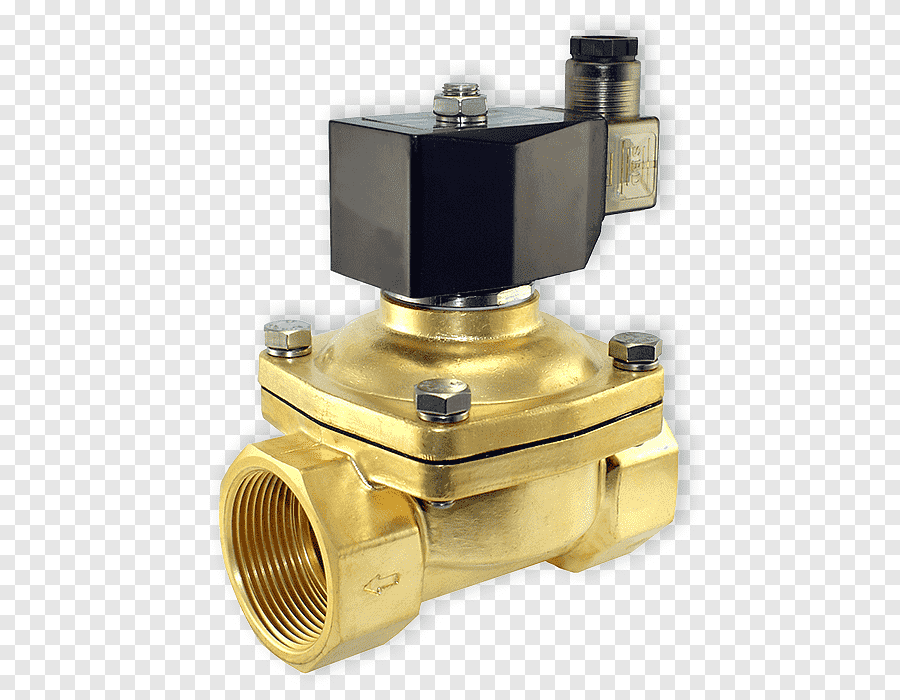
- A 12V food-grade, NO (Normally Open) solenoid valve. I used this one, which is normally closed without power and works well for water applications.
- A 12V power supply to power the solenoid valve.
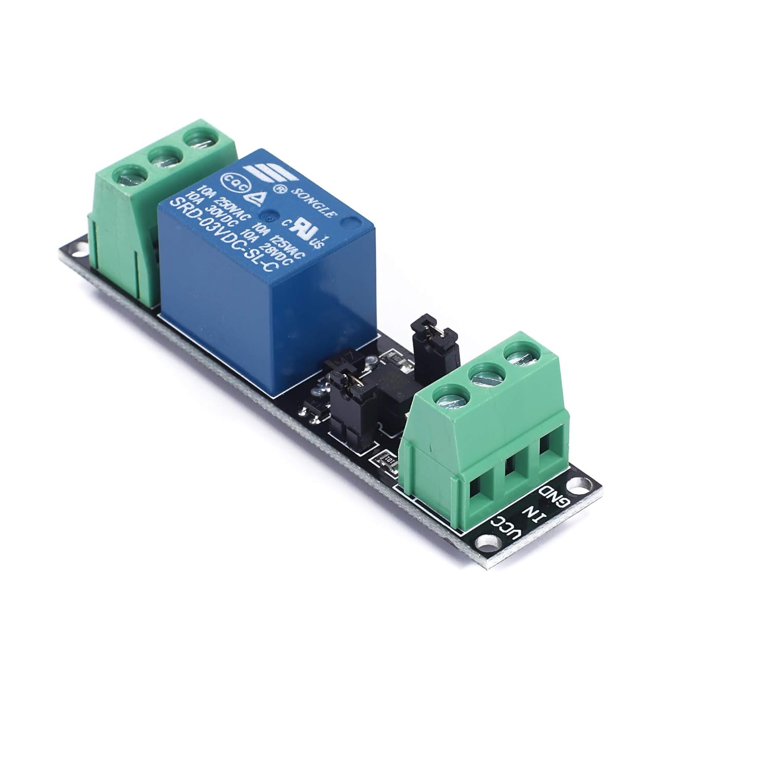
- A relay module to control the solenoid valve from the Raspberry Pi. To keep this simple, I’ll use a pre-made one instead of building my own. I used this one.
- A water sensor to prevent overflows. I used this one, but anything that can set a digital input high or low will work.

When you launch a Krill App and are on the same network as your Krill Server the app will automatically detect the server and prompt you to connect. You can select the Krill Avatar for menu options to manually connect or enter the API Key needed to connect to the server for the first time. Learn more here about setting up your Krill Server.

When you select a node on a Krill Swarm, the avatar will show you the available menu options for that node based on what it is. Since I clicked on a Raspberry Pi, the option to configure a Pin is available. Selecting the Raspberry icon adds an unconfigured Pin to the swarm.
These pre-assembled relays are great time savers. Just connect the output pin you configured with Krill and the 3.3V pin to the relay, along with ground. Use a separate 12V power supply's positive to the other end. Connect your Pi's ground and your power supply's ground to a common bus.
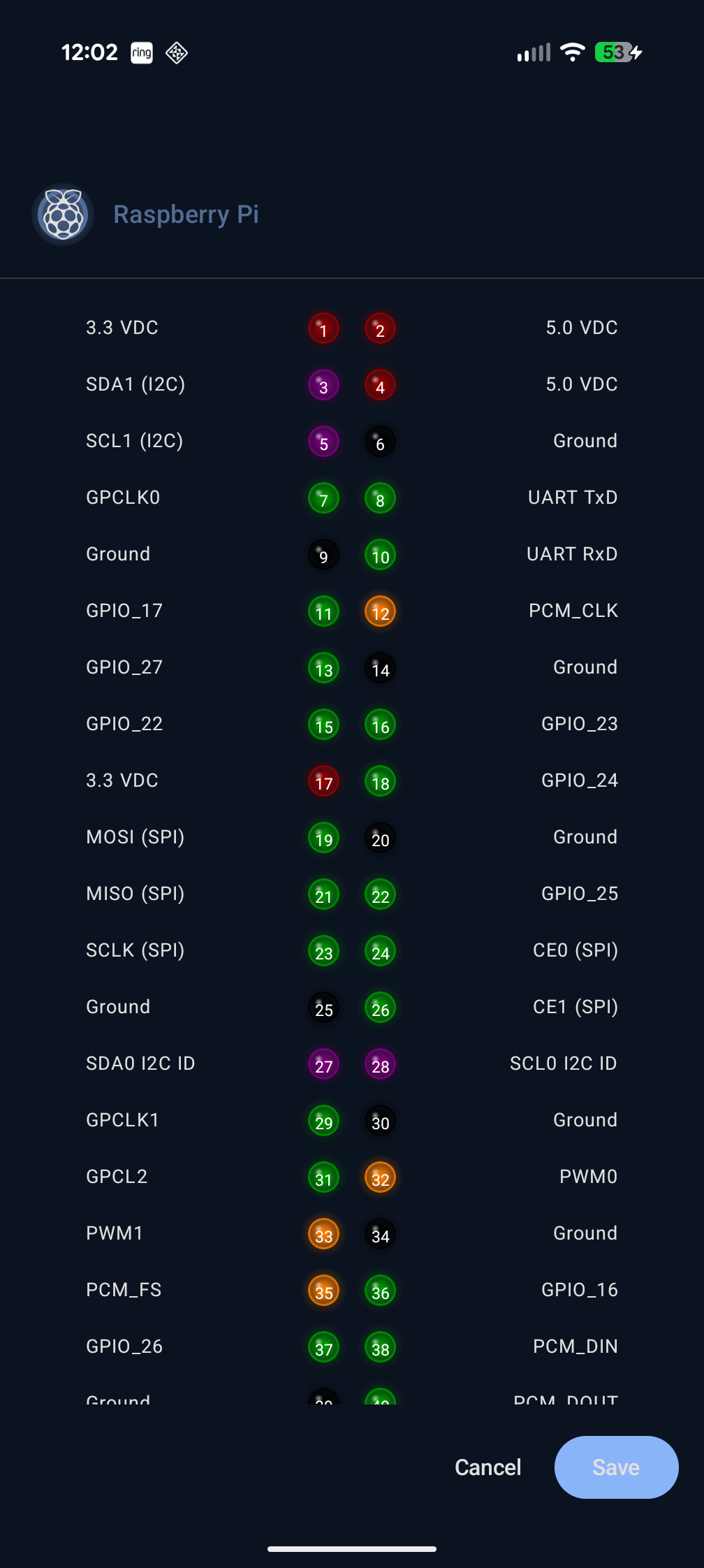
We can now configure the pin to control our solenoid valve. Selecting the Pin icon brings up the Pin configuration menu where we can specify the pin number, mode, and other options like startup/shutdown modes or whether it's an input or output pin.
These 12V solenoids are perfect since they are normally closed when there's no power. I also add a pressure control valve before the solenoid so the system I'm building isn't getting the full water pressure from the house.
Krill works by adding nodes to your swarm and configuring them to read and write data from different data sources, or execute child nodes below them when conditions are met. Selecting the node I want to add to or configure shows me the available options for that node. Since I clicked on a Pin node, the option to configure a Logic Gate is available.
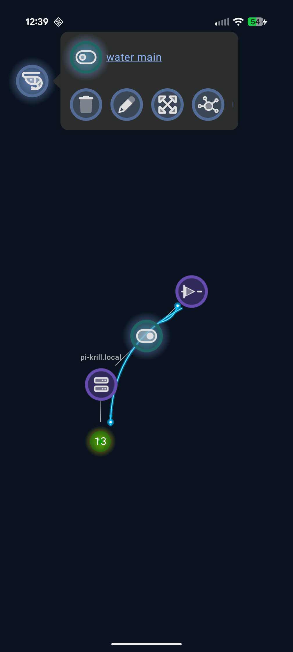
You can also add a toggle switch and a logic gate with that switch as its source. That's all you need to create a toggle that will execute a logic gate to set the pin to HIGH or LOW! The flashy blue arcs show a visual of data flowing between nodes. Note: you can edit a Toggle or Button by long-pressing on mobile or right-clicking on desktop and web interfaces to avoid running them.
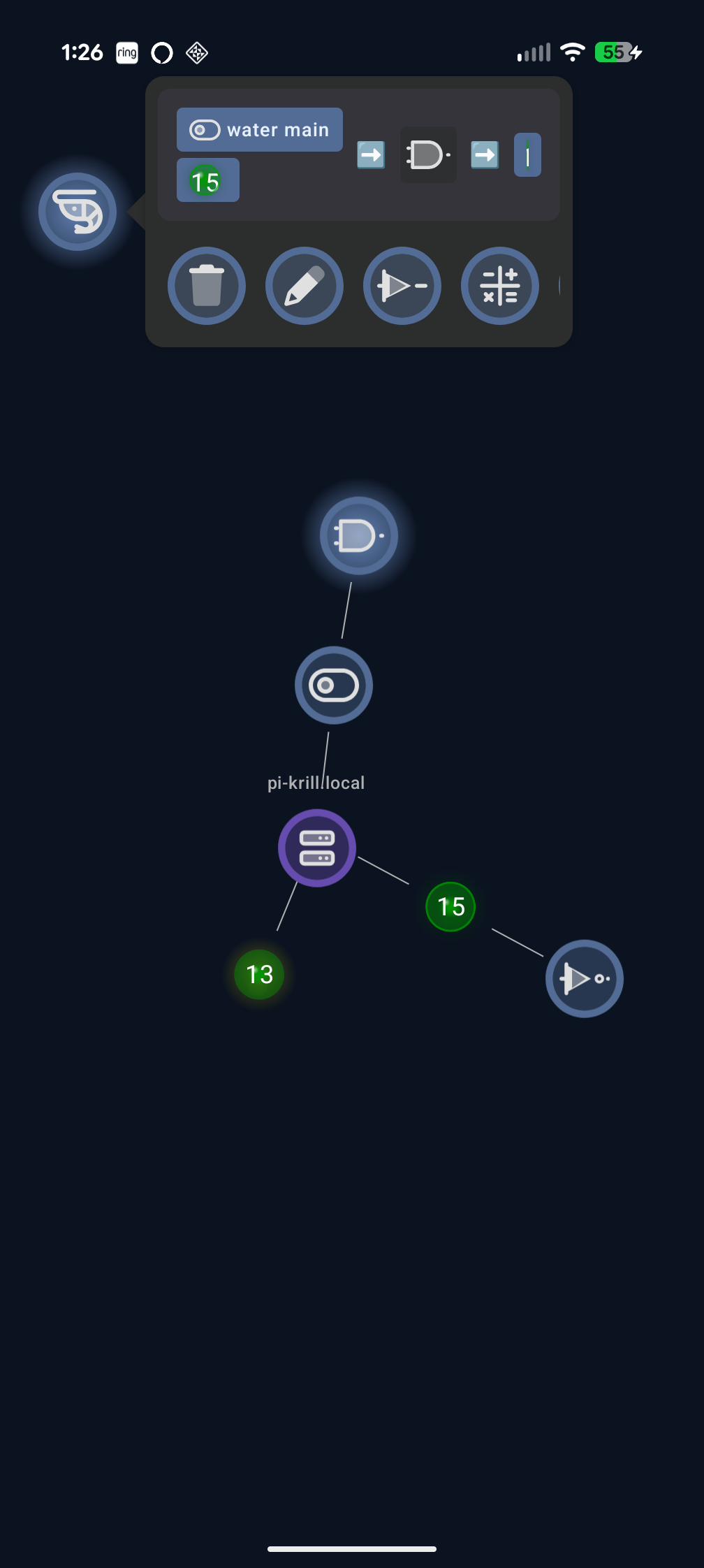
Next I added a second input pin for the water sensor to prevent overflows. The water sensor is a simple digital sensor that sets the pin LOW when water is detected and HIGH when no water is detected. I switched the BUFFER logic gate to an AND gate so that the solenoid valve will only open when the toggle is ON and no water is detected by the sensor.
I also added a NOT gate to flip the toggle to off if the water sensor is HIGH, turning off the solenoid if it happens to be running and water is detected.
There’s a lot more to explore with Krill, but this is just the beginning. In the next part of this series, I’ll show you how to use Krill to control water pumps and valves for our aquarium and hydroponic systems, including:
- Lambdas that can run Python scripts on your server to do anything you want using input and output data sources from other nodes.
- Calculations to use sensor data in a mathematical formula to generate new data to use as input for other nodes.
- CRON Timers to create schedules for your pumps, valves, and sensors.
- Compute Summaries to aggregate data from multiple sensors to make decisions.
- Filters and Triggers to only execute nodes when certain conditions are met or filter noise.
- Server-to-Server communication to connect multiple Krill Servers together for large-scale systems.
- MQTT Pub/Sub to connect to thousands of third-party sensors and devices, including Zigbee2MQTT.
- Read and Write to Serial Devices to connect to Arduinos, QTPYs, and other microcontrollers.
Next in the Series
Now that we have water flow control and leak detection, the next step is feedback control. In the CO2 Reactor with Color Sensor post, I build a DIY CO2 injection system that reads pH indicator color with a TCS34725 sensor and automatically shuts off CO2 when levels get dangerous.
Related
- The Movement of Water — Series overview
- Relays and Solenoids — Controlling water flow with GPIO
- CO2 Reactor with Color Sensor — Automated feedback control with color sensing
- Getting Started — Install Krill and create your first project
Last verified: 2026-04-06